$1 Trillion+ in volume processed
Bsmce04u-pp Manual ((better)) Jun 2026
The most trusted smart wallet infrastructure. Modular, programmable and battle-tested.


Eliminate single point of failure. Distribute access control across multiple owners

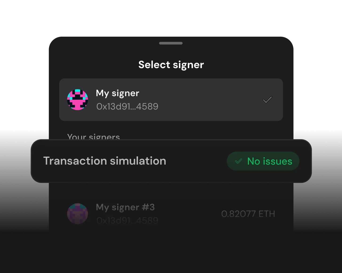
Scan risks and simulate transactions before they execute

Set daily spending limits, approval thresholds and role-based access

Invite team members to manage and track multi-chain Safe accounts together

Cut gas costs by bundling complex transactions into one signing step

Defend against private key compromises and setup thresholds
Safe is among the most audited and battle-tested contracts on Ethereum.
No black box for your treasury. Independently verify all changes
Never loose access to your account by nominating a guardian
Safe, like Morpho, makes security its top priority. That's why we see strong alignment and confidence using Safe for Morpho's daily operations across multiple networks, making it a key building block of our operational stack.
Merlin Egalite, Co-Founder Morpho Labs


The (often referred to as the Bitsensor or "Red Board") is a popular 4-axis USB motion control card designed primarily for use with Mach3 or DrufelCNC software. This manual covers the essential hardware features, software installation, and pin configurations required to bridge a standard Windows PC with CNC hardware like stepper motors and spindles. 1. Hardware Overview and Key Features
In the world of industrial automation and power management, having precise, technical documentation is critical for operational efficiency and safety. The serves as the definitive guide for users operating this specific power control module. Whether you are installing, troubleshooting, or performing routine maintenance, this manual provides the necessary technical specifications and procedures.
Features 4 isolated relay drive outputs (OUT1–OUT4) to control spindle start/stop, coolant pumps, or other accessories. Spindle Speed Control: Provides a 0-10V analog output
Capable of generating high-frequency pulses for rapid movement. Multi-Axis Support: Often used in 4-axis configurations.
To control the speed of a spindle with a Variable Frequency Drive (VFD), wire it this way. For a PWM (Pulse Width Modulation) signal instead of analog 0-10V, you may need to connect the ACM and DCM terminals and provide 5V or 10V to the appropriate pin. bsmce04u-pp manual
: Much of the "official" documentation is actually provided by software vendors like DrufelCNC or community-maintained guides on Scribd .
To ensure the hardware communicates correctly with the software, you must configure the Ports and Pins.
Even with the manual in hand, engineers often misinterpret certain details. Avoid these pitfalls:
Before wiring, verify that your hardware parameters match the operating tolerances of the board: Mach3 USB Motion Card (BSMCEO4U-PP) Installation Manual The (often referred to as the Bitsensor or
No. The unit is rated for pollution degree 2, indoor use only (0 to 95% non-condensing humidity). An IP54 enclosure is required for sheltered outdoor use.
Manufacturers often void warranties if damage occurs due to improper installation or operation that violates the manual’s instructions.
Connect the negative wire of your power supply to the (Digital Ground/Common) terminal. Go to product viewer dialog for this item.
Explanations for common LED error patterns. Hardware Overview and Key Features In the world
| Issue | Possible Cause | Potential Solution | | :--- | :--- | :--- | | | No power to the board or drivers; incorrect Mach3 plugin configuration; step/dir wires are swapped. | Check the power supply voltage to 24V and DCM (12-36V). Verify the plugin is enabled in Config > Plugins . Review wiring against the driver's documentation for correct STEP/DIR connections. | | Axis jitter or vibration | Step pulse frequency in Mach3 is too high; microstepping settings on the driver are mismatched; power supply is inadequate for the load. | Lower the Steps per value in Motor Tuning . Adjust the dip switches on the driver for a lower microstep setting. Check voltage with a multimeter. | | Spindle speed is erratic | The 0-10V control signal is noisy or unstable. | Install a 22 µF, 25V electrolytic capacitor between the AVI and ACM pins on the VFD. Verify proper grounding of ACM . | | E-stop or limits not working | Input pin mapping in Mach3 is incorrect; switch is wired to DCM and the correct input; the Active Low setting is wrong. | Assign the correct input number (I1, I2, etc.) and the correct port in Config > Ports and Pins . Ensure one side of the switch is connected to DCM . Toggle the Active Low setting for the input. | | Board not detected by PC | USB cable is faulty or not connected; driver issue in Windows. | Try a different USB cable and a different USB port on the computer. The device should appear without a driver; look for an "STM32" device in Device Manager. | | Axis remains red in Mach3 | Reference switches are not triggered; missing reference command; motion controller is not enabled. | This can be normal until a reference command is given. Jog the axis to trigger a home switch. Add a G28 or similar command to the code. Check the plugin is properly installed and enabled. | | Inconsistent or "jumpy" motion | EMI (Electromagnetic Interference) from the VFD spindle. | Use shielded cables for all step/dir signals. Keep high-power and signal wires separated. Add ferrite beads to the USB cable. |
While highly efficient, the board often ships from online retailers without physical documentation. This comprehensive technical manual covers specifications, physical wiring layouts, Mach3/DrufelCNC integration, and advanced system optimization. Technical Specifications & Features
(Only for multi-unit systems):